Power supplies contribute to EMI, but are not always to blame for EMC failures
In a typical product there will be multiple sources of noise and nonlinear components that will exacerbate emitted noise of the system. Whilst PSUs are one source of noise there can be many others and unless best practice is applied even the ideal power supply will not save you from EMC failure.
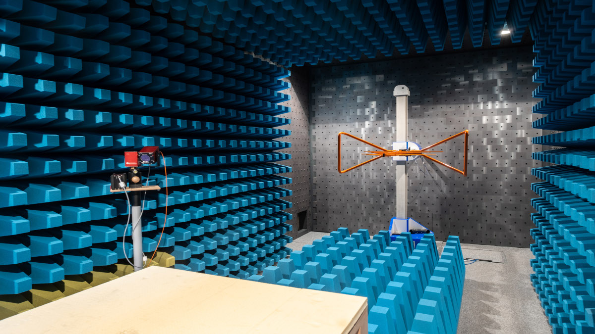
Electromagnetic Compatibility emission requirements of a system will be outlined in the relevant standard e.g., EN55032 for standard ITE applications EN55011 for medical equipment. Conformity to these relevant standards will mean you can presume conformity to the directive (CE) or relevant regulation (UKCA) for your end system. All external power supplies will have a complete EMC test report and declaration to the relevant regulation or directive since they are “finished products”. The test is conducted using a resistive load, but in reality it is rare that the powered application is linear. So, despite the external power supply holding its own EMC approval, when used in conjunction with the system it is the entire system that needs to be re-tested to show it conforms to the relevant standard.
Component power supplies: chassis mount AC-DC converters, DC-DC converters, board mount encapsulated AC-DC converters or modular power supplies do not have “complete approvals” for safety or EMC, since they are yet to be installed into a finished product. Whilst LVD (low voltage directive), CB (IEC), UL (Underwriters laboratory) reports and EMC reports may well be available as partly completed documents the successful integration of them into your system will determine your ultimate type test approval success. For example, simply combining CE, UKCA or UL marked components together in a system will not mean your end system can be CE, UKCA or UL marked!
Cable routing
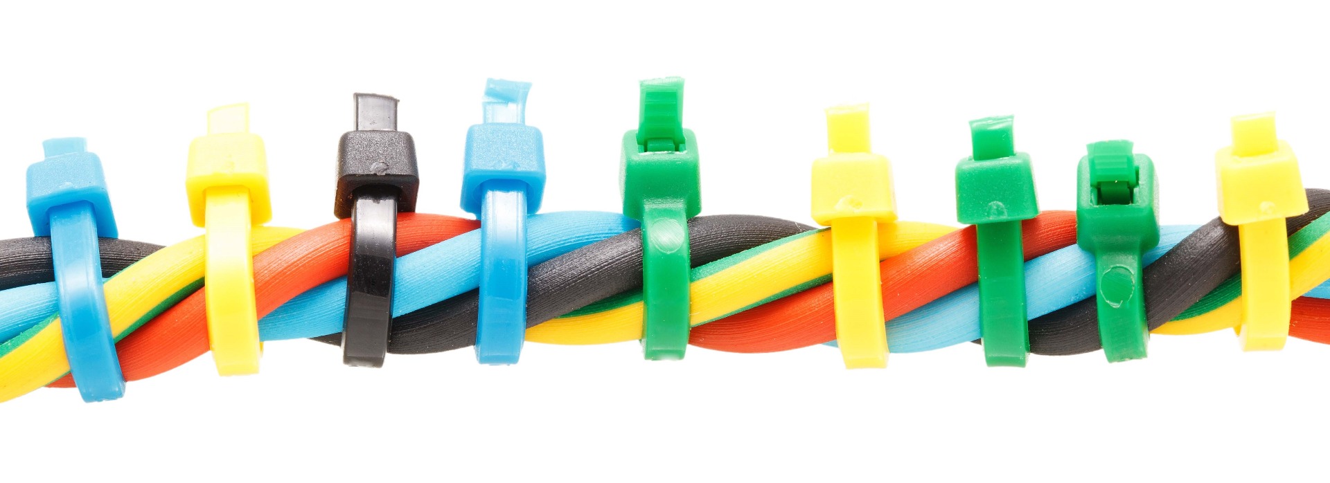
The first thing that I look for in a design is good cable routing. The hard work that has gone into the PSU or application board design can easily be ruined by poor cable layouts. The DC output of a power supply should be kept separate from the input. Whilst it may look neat or convenient to zip tie or shrink them together the switching noise on the output is bypassing the filtering / isolation that the PSU circuit is designed to mitigate. The switching noise will be parasitically coupled to the neighbouring input cable resulting in further amplification of radiated noise and create conducted or radiated emissions back upstream. Twisting the input cables will increase the common mode noise rejection (immunity to the noise), separation and screening with shielded cable is also affective forms of mitigation. For the same reason, running cabling over or under the PSU will result in amplified EMC emissions, so it is crucial that this is avoided.
Board level sources
When PCB bord layouts are created many aspects need to be considered in parallel for a successful design including but not limited to; cost, thermal management, mechanical fit, track size and shape, signal integrity and noise (where coms are involved primarily). All too often EMC is not considered and is mitigated afterwards with more global approaches with cable ferrites, input filter or containing the board in a faraday cage. Identifying “hot loops” of the board where there is a large and rapid change in current is a primary focus, since it is these parts of the board that will result in the unwanted emissions.
V=L(didt)V=L(didt)
Reducing the voltage offset according to the above equation, by either changing the speed of current change or the inductance of the hot loop will result in reduced emissions. In a boost converter the hot loop is in the primary and in a buck converter it is in the secondary where we find the large change in current:
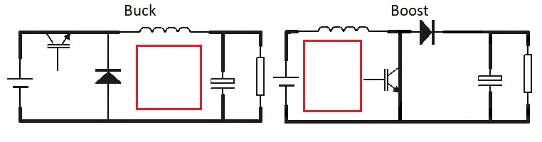
The loop size as well as its inductance have effects on the emission amplification. The use of wider tracks forming smaller loops and low ESL capacitors all contribute to lower emissions since the inductance is reduced.
Shielded components
Inductors and transformers are essential components in power conversion circuits and handle switched loads. By their nature and use case in the design they of course have inductance and will contribute heavily to the EMI. The use of shielded inductors and transformers will significantly reduce their emissions.
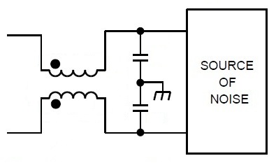
Processors, point of load converters and of course MOSFET switches all turn circuits on and off at great speed and thus will contribute to the noise spectrum of the system. The use of Y caps and a common mode choke are a powerful tool in combating the common mode noise (noise that is applied to both positive and negative rails) that finds its way to earth.
Ferrites

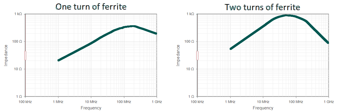
Ferrites should be added at board level in the PCB design where localised emissions are present to attack the issue at source before it couples on to other parts of the circuit. Cable mount ferrites should be a last resort approach as this treats the affects but not the cause of the noise. Often these are added to designs where EMC has not been a continuous focus in the design and reviewed at every milestone. They may not mechanically fit in the design if added retrospectively and be a more costly solution. A bigger ferrite does not mean better! The material that the ferrite is made from will lend itself to certain frequency bands. When choosing a ferrite it is important to locate the conductor that the emissions are coming from and understand what frequencies are needing attenuating and how much you need to attenuate them by. Knowing this and of course the mechanical fit an affective ferrite can be specified as the size of the conductor is reviled. Typically, lower frequencies <100mhz are associated with the AC cable, since this is inherently long, so if you have emission failures in this region begin your search there. Looping the conductors around the ferrite will increase its attenuation and may mean only one ferrite is required to achieve the desired effect, however this does change the shape of its impedance curve at different frequencies, transposing the peak to the lower end of the spectrum.
Ground planes and faraday cages
EMI from switching sources can be contained in a design by sinking it to a ground plane or containing it inside a faraday cage. When covering a noise source care must be taken to ensure that the components remain cool, either via the use of conduction, forced convection or simply natural convection with holes in the metal cover. CAUTION: The shape of the slots or holes in the metal cover may act as an ariel and amplify the radiated emissions as opposed to containing it!
Ever wondered why you do not get cooked in front of a microwave? In the glass is a matrix of wire that acts as a shield. The diagonal measurement across the grid squares is too small for the microwaves to escape. The same principle can be applied to your thermally optimised enclosure.
f=C/λ
(Where C is the speed of light 2.998x10⁸m/s)
The frequencies being emitted from clocks, power supplies or any other switching sources are to be considered primary emitters. The higher the frequency the shorter the wavelength and a good rule of thumb is to ensure that the cooling apertures in the cover are no larger than 1/20th of the wavelength. Any larger than this the aperture runs the risk of becoming a slot antenna. Remember for a rectangular slot this is the diagonal measurement from corner to corner and for a hole its diameter.
Please contact Fidus Power to help guide you from the beginning of your design for best chances of EMC compliance. If you are currently failing EMC in your design, please get in touch with us for some gratuitous helpful advice.